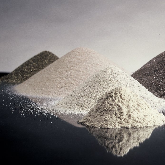
How it’s Made: Premium Grade Virginia Mullite
by Steven Ashlock
Director of Technology and Research, Ceramic Engineer
Kyanite Mining Corporation
Austin Scheer
Ceramic Engineer
Kyanite Mining Corporation

Abstract
The selection of refractory flours and stuccos used in investment casting vary based on the alloy poured, temperature at which they are poured, and the hold time of the alloy at the pour temperature. Within a particular refractory mineral category, deposit characteristics, as well as beneficiation techniques can result in different raw material properties. In addition, varying levels of impurities can greatly differentiate mineral sources among suppliers. Contaminants such as iron (Fe2O3) and the alkali/alkaline earths (Na2O, K2O, CaO, MgO) can have a dramatic effect on the high temperature performance of investment casting shell molds, impacting casting quality and their as-cast dimensions. For example, impurities in the facecoat can lead to mold-metal reactions that effect the surface finish of the casting (increased rework) and the shell removal. Impurities in the backup layers can lead to decreased strength, increased thermal expansion, and increased creep, which again negatively affect the dimensional stability of castings. Understanding the source of the impurity, the location of impurities in the shell, and their potential impact is crucial to consistent casting quality, yields, finishing labor (rework), and process control.
Iron oxide is one of the most problematic impurities in refractories. Iron acts as a flux, causing glassification of the refractory which leads to high temperature creep (shell bulge); ultimately impacting dimensional stability of castings. This paper will focus on the processing of Virginia MulliteTM and how the complex beneficiation process of the ore body produces a consistent raw material with very low iron content. Recent improvements in the purification process have led to the production of new Premium Grade Virginia MulliteTM which will also be discussed in detail. These process changes have enabled a lowering of the iron oxide content from a maximum of 0.75% to less than 0.2%. Testing was conducted to examine the effects of the lower iron content on the physical properties of the shell. Results indicate that a reduction in iron oxide in the shell refractory leads to increased creep resistance in the shell. This produces a more dimensionally stable casting, improved yields, and help reduce finishing labor costs at the cast house.
Introduction
Investment casting is the process of creating a complex metal shape by encasing wax in a ceramic refractory shell and removing the wax to create a hollow cavity into which molten metal can be poured. The shell must be able to withstand the high temperatures and pressure of the investment casting process and maintain its constant shape (pattern geometry) in order to produce dimensionally consistent castings. There are many refractory raw materials used in the investment casting industry today; some of these include zircon, alumina, fused silica, and aluminosilicates. Each material has its advantages and disadvantages that must be considered when selecting a mold material. Physical properties, such as maximum usage temperature, creep resistance, strength, thermal expansion, cristobalite formation (health and safety), and the overall relative cost must be considered.
Selecting the proper raw material type is the first step; the second is to compare different sources. The obvious and initial consideration is cost and availability, but the origin of the raw material is of great importance. No two deposits are identical in terms of purity and performance. The naturally occurring purity of the deposit, the amount and type of impurities, mining techniques, and mineral processing techniques can vastly affect how the material will perform in the shell and ultimately impact the scrap rates and the quality of the casting.
A good example of how the differences in natural geology and processing techniques affect the performance of the material can be seen in the aluminosilicates. As the name suggests, aluminosilicates are minerals made up of alumina and silica in various ratios. Pure silica and pure alumina are both very refractory raw materials but have their drawbacks. Pure silica has a high melting point of 3135°F (1723°C).1 However, impurities in silica act as a flux and drastically reduce the melting point, forming glass. This glass will begin to soften and flow which will affect the dimensional stability of the shell and can cause it to bulge. This can lead to castings that are out of dimensional tolerance. Impurities in a face-coat can result in a glassy phase sticking to the surface of the casting leading to surface defects, scrap, or increased rework. Alumina is also a highly refractory material with a melting temperature of 3730 °F (2054°C).1 It is one of the pillars in the world if ceramics for its high temperature properties and is more resistant to fluxing than silica. However, pure alumina performs poorly under thermal shock conditions. This can lead to shell cracking and positive metal defects on the as-cast surface.
One way to combat the potential issues of pure silica and/or pure alumina is to mix the two materials together. In Figure 1, you can see the Silica-Alumina phase diagram.2 There is only one thermodynamically stable intermediate phase in the alumina-silica system: mullite. The ratio of three parts alumina to two parts silica makes stoichiometric mullite with an alumina content of 72 weight percent. While the melting temperature of mullite is lower than alumina, it still exhibits excellent high temperature properties. Mullite has a melting point of 3435°F (1890°C) and is one of the best refractory ceramics for thermal shock resistance.1

Figure 1: The Alumina-Silica Phase Diagram can be used to determine the hot properties of materials containing different ratios of alumina and silica.
Pure mullite is rarely found in nature due to its high temperature/low pressure formation conditions. The first samples of the 3:2 aluminosilicate were discovered by Bowen and Grieg in the 1920’s.3 They noticed the material in lava flows on the Isle of Mull where clay sediments had come in contact with the hot magma. The new mineral was given the name after the island.3 Its rarity as a naturally occurring mineral means that it is not mined for industrial purposes. While not stoichiometric mullite, there are many different aluminosilicate minerals. Examples include the clay minerals (kaolin, mica, pyrophyllite, etc) and the sillimanite group of minerals.
Mullite used for industrial purposes must be created using precursor minerals. There are two main methods: in-situ mullite formation and the creation of mullite aggregates. Examples of mullite creation in situ in ceramics go as far back as 1500-1000 BC in Chinese pottery.3 In situ formation of mullite is a common practice in the ceramics industry to this day.
The investment casting industry uses mullite in both aggregate and powder form. Most of the aggregate mullites in the industry today are made by mixing, extruding/spheredizing, and calcining clay minerals to form the mullite. These aggregates can then be ground to make the flours used in slurries. These mullites are frequently categorized by their overall alumina content. Mullites with alumina contents ranging from 40-70% are commonly found throughout the industry. The major mineral phase of these aluminosilicates is mullite with the remainder comprised of either quartz, cristobalite, or amorphous silica. Selecting the appropriate alumina percentage is critical in order to achieve the desired properties of the mold at temperature. It is commonly believed that the higher the alumina content, the higher the maximum usage temperature of the mullite. While this is generally true, the impurities in mullite can have a greater effect on the usage temperature than the overall alumina content.
While making mullite from clays is the predominate method of obtaining mullite, it is not the only way: industrial grade mullite is also made by calcining the sillimanite family of minerals. The sillimanite family of minerals are aluminosilicates with a 1:1 ratio of alumina and silica. The three industrially important members of the mineral family are kyanite, sillimanite, and andalusite. These three minerals are all polymorphs of the 1:1 chemical composition. The pressure and temperature of formation determines which of the minerals is created. The Pressure-Temperature phase diagram, Figure 2, is shown below.4
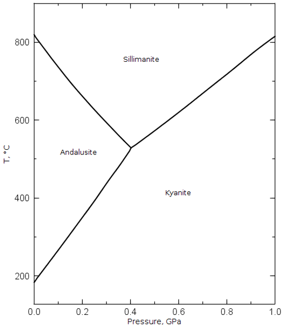
Figure 2: This Pressure-Temperature Phase diagram shows the conditions required to form the different minerals in the sillimanite group.
When heated, the sillimanite group of minerals undergo a phase transformation to mullite plus excess silica. This reaction is shown in Equation 1.

The temperature of this phase transformation differs in each of the three sillimanite minerals.5 When heat is applied, the Al3+ cations change coordination number. This causes the rearranging of the atoms to form the more open crystal structure of mullite. The kyanite crystal structure is the least ordered of the three and thus has the weakest chemical bonding. This means it requires the least heat energy for the phase transformation to begin. Table 1 shows the conversion temperatures and theoretical expansion rates of the three minerals as they convert to mullite.6 The lower temperature requirement for conversion makes kyanite an ideal candidate for the production of mullite.

Virginia Mullite™: How It’s Made
The Deposit
In order to understand how to make Virginia MulliteTM, we must first explore how its precursor mineral, Virginia KyaniteTM is made. The first requirement for mining and refining industrial grade kyanite is to find a source mine. Silica and alumina are the two most abundant oxides on planet Earth, making up 59% and 15% of the earth’s crust respectively.7 Yet, finding these two oxides in the correct ratios (that have been subjected to the necessary heat and pressure regimes) to form the sillimanite family of minerals is more uncommon. However, that is not to say that the sillimanite family of minerals are rare. They can be found on almost every continent on the Earth. What is rare, is a deposit that is not only large enough to be economically viable, but one that has a high purity ore body. Pure in this sense typically means not only lacking in impurities but also the other sillimanite minerals. Once such a deposit has been found, the real testing begins. Even if a deposit is large and pure, it does not mean that it will be able to produce industrial grade material. The geology of the deposit and the other minerals present will determine how difficult it is to remove the kyanite from the ore body and its associated minerals-even in trace amounts. When it comes to kyanite, Willis Mountain in Dillwyn, VA is a world-class deposit that is suitable for the production of industrial grade kyanite. The mining and production of industrial grade kyanite (and mullite from kyanite) has taken place at Willis Mountain for over 60 years.
Willis Mountain is located in Central Virginia about seventy miles west of Richmond and fifty miles south of Charlottesville. The Willis Mountain deposit resides in the geological occurrence known as the Whispering Creek Anticline. The deposit is made up of two halves: Willis Mountain itself and East Ridge, which is the other half of the anticline. The deposit was formed around 465 million years ago during the Middle Ordovician Period.8 The predominant theory is that venting of mineral rich fluids deposited clay minerals. That material was subducted to a depth conducive to form the minerals seen today. The deposit was then thrust upwards to the surface and then truncated which created the exposed east and west legs of the formation.8 The ore body is made up of kyanite-quartzite rocks.
Willis Mountain rises 475 feet above the surrounding countryside and runs for about 1.75 miles. The ore body contains 20-30% kyanite. The main impurities are quartz, several varieties of mica, iron oxides, iron sulphides, and a multitude of minor minerals. The deposit runs near vertical through the entire height of the mountain, and is, generally, 120 yards thick through its entire length. Willis Mountain has been continuously worked since the late 1950’s, but the majority of this large orebody remains untouched to this day. It is estimated that well over 50% of the Willis Mountain ore remains.
The East Ridge deposit, adjacent to Willis Mountain, also runs for 1.75 miles. The ridge is shorter than the mountain, rising up from the surrounding countryside about 300 feet. The East Ridge deposit contains more impurities than the deposit on Willis Mountain. Higher amounts of iron sulphides and clay minerals are common, and a wider variety of iron oxides and micas are seen. The vein at East Ridge is also thinner than the Willis Mountain vein and runs at a 30° angle instead of vertically. Mining at East Ridge began in the late 1970s, and substantial reserves remain in this part of the orebody also.
The lifetime of these two Virginia deposits is difficult to assess and has never been definitively determined. It is clear that there is enough exploitable ore to continue mining for many generations at current production rates.
Mining and Comminution
Mining is done from both the above-mentioned deposits on a single daylight shift, five days a week. Blasting occurs as needed but typically happens once or twice a month at each deposit. Blasting is done by filling drilled holes (usually roughly 30 feet deep) with a liquid explosive. Rocks that remain too large to move after the blast are broken down by a rock breaker. Loaders pick the material up and put it in the back of haul trucks that bring the material to a single jaw crusher where the ore from various parts of the two quarries is blended together. The average kyanite percentage of the ore runs around 20-25%, which means that roughly 650,000 tons of ore must be mined and processed each year to meet the 100,000 – 120,000 tons of annual demand for the company’s purified kyanite and mullite products.
The first step in the comminution process is a large jaw crusher, where rocks weighing several tons each are reduced in size to ones weighing only a few dozen pounds. After this, the material passes through several further stages of crushing (mainly gyratory) and screening to progressively reduce the size of the ore to roughly one inch by down in size.
Wet Processing
After dry comminution, the ore stream is fed into what is called the Float. It is called “the Float” as several of the steps in the wet processing of the material involve froth floatation, but many other size reduction, size sorting, and beneficiation technologies are involved in the removal of impurities in this part of the process. This wet processing, as the name suggests, is very water intensive, using 7,000 – 8,000 gallons per minute, and runs 24 hours a day, usually for five days a week. There are well over twenty steps in this part of the beneficiation circuit (rod mills, ball mills, hydro-sizers, hydro-cyclones, screens, float cells, spirals, extractors, etc.), and at the end of the elaborate set of mineral purification steps the all the various forms of clay & dirt have been removed, as have almost all of the pyrite and mica. Alkali and alkaline earth oxides have been reduced to less than 0.05% and the titania to around 1.5%. The quartz content has also been reduced to 4-6%. The iron oxides are the only impurity that have been left untouched in this part of the process, and they make up anywhere from 5%-10% of the “float concentrate” at this point in the process. Their removal takes place at the next part of the beneficiation process.
Dry Processing
The removal of the various naturally occurring forms of iron occurs in the dry processing phase of the company’s beneficiation circuit. The damp “float concentrate” is dewatered in several steps, and then is fed into a fluid bed dryer, being mixed and blended along the way. The homogenized material falls into the top chamber of heated fluidized bed, similar to those used in stucco application at some foundries, where the material is fully dried. It then makes its way into another chamber of this vessel where it is heated to over 1000°F (540°C) before undergoing a special process to convert all of the various iron oxides into a magnetic form. After which, the kyanite/iron mixture is cooled in a rotary cooler. Once it has cooled down to less than about 250°F (120°C), the material is run through several banks of magnets: some low intensity permanent magnets, some high intensity variable magnets, as well as some rare earth magnets. These banks of magnets bring the total iron content down into the 0.4%-0.6% range. This part of the process runs for extended campaigns 24 hours a day, seven days a week in order to prolong the lifetime of the refractories.
Recently, new processes have been developed in order to further reduce the iron content of a portion of the company’s kyanite production. This has allowed for the production of an even lower iron oxide product: Premium Grade Virginia KyaniteTM. The iron oxide content in this material is less than 0.2%. It is these new separation techniques that create the lower iron oxide containing kyanite which is the precursor for Premium Grade Virginia MulliteTM.
Calcination
The Premium Grade Virginia KyaniteTM is taken by truck to one of our two calcination plants. The kyanite is put through a rotary kiln where it is exposed to temperatures in excess of 2700°F (1480°C). There are three kilns in operation. The heating of the kyanite causes the crystal structure to rearrange and form mullite, as previously discussed. This reaction was shown in Equation 1. The silica produced as a byproduct of the reaction is very fine and amorphous. This amorphous particle is stuck to the side of new mullite crystal blades. When kyanite is converted to mullite it expands seventeen volume percent. The mullite also maintains the very high aspect ratio (acicular or needle shape) of kyanite through the conversion.
Grinding and Sizing
After calcination the Premium Grade Virginia MulliteTM will take one of two routes: screening for stuccos or milling for flours. To make the stuccos, some of the mullite is sent over vibratory sieves. This is a multi-deck sieve stack that creates both the 20x50 and the 50x100 stucco products. The elongated needle shape of the mullite makes this a difficult process to control because the blades can stand on end and pass through the screen. Controlling the feed rate and vibration frequency are very important to maintaining a consistently screened product.
The rest of the Premium Grade Virginia MulliteTM goes to a special ball mill for grinding. This ball mill is lined with granite and uses alumina milling media. Using steel balls or liners would negate the effort put into making a lower iron product. The material exiting the mill passes through an air classifier to send any large particles back to the mill for further grinding.
Testing
Testing throughout the process is vital to make a consistent product. Testing begins at the mill side of the float to determine the kyanite percent of the raw ore. Dozens of tests are done in the flotation building to check on the level of beneficiation of the kyanite from the other minerals. At the dryer, particle size testing is done to check the coarseness of the product. A field XRF unit is also used to monitor the iron removal process. Helium pycnometers are used at the kilns as a field test to check to see if the kyanite was completely converted to mullite during the calcination process.
All material is sent to the main Quality Control Lab for final testing. Each bag of product is tested for particle size distribution, chemistry, and mineralogy. For stuccos, a Ro-Tap is used to screen size the product. For finer meshes, an air sieve is used. Laser light scatter analysis can also be done on the flour products using a Microtrac particle size analyzer. Chemistry is checked on an x-ray fluorescence analyzer. An x-ray diffraction unit is used to check the mullite for any unconverted kyanite and determine the presence of other minerals or compounds of interest, such as cristobalite content.
Why it Matters
Producing mullite by beneficiating kyanite from the ore body and then calcining is a time consuming and meticulous multi-step process. However, the effort is worth the time and resources spent as this method of mullite production creates a final raw material with some unique and useful properties. There are several differences between mullite made via calcination of kyanite versus mullite made from calcining clay minerals. For one, each individual mullite crystal produced comes from a kyanite crystal instead of an agglomeration of crystals. This allows the mullite particles to have a high aspect ratio. When agglomerated to form an aggregate, the natural aspect ratio of mullite is neutralized by the shape of the aggregate. Kyanite is a blade shaped mineral. Mullite made from kyanite maintains this aspect ratio throughout calcination. The high aspect ratio of the particles has been shown to increase hot MOR strength, reduce mold splits (cracking), and has led to the reduction of the number of backup coats needed on the mold.
Another difference is the homogeneity of the mullites. Impurities in mullites produced from clay minerals are often well dispersed throughout the entirety of the aggregate. While homogeneity is typically a good thing, this can be a detriment concerning creep resistance. If the impurities are dispersed throughout the material, then the aggregate will creep. Mullite from kyanite, on the other hand, is a single blade particle. The impurities in the material are stuck to the sides of the kyanite/mullite crystal surface and are thus localized. This means that a small area of the grain may creep, but the rest of the crystal, where the impurities are not located, will not. Stacking several of these blades together will spread that creep around and lead greater creep resistance than a typical blended aggregate mullite material.
While mullites generally exhibit excellent creep resistance, the iron content limits the maximum usage temperature before the on-set of creep. Iron oxides act as a flux when combined with silica which drastically lowers the melting and softening point. This forms glass, which is fluid, and allows the shell to creep. It is shell creep (bulge) that can lead to poor dimensional control so castings may be out of tolerance to customer specifications without additional rework. Small changes in iron content can have very large effects on the usage temperature and the stability of the shell. This concept is what led to the production of the Premium Grade Virginia MulliteTM. This material has an iron content of less than 0.2% vs the standard Virginia MulliteTM that contains a maximum of 0.75%.
Dilatometer testes were done in order to examine the effect of iron on the creep resistance of various mullites. A listing of these mullites can be found in Table 2. The alumina, silica, iron, and the alkali/alkaline earth oxides contents are shown. Attempts were made to test materials with a wide variety of alumina contents. The dilatometer temperature profile is shown in Table 3.


Figure 3 shows the temperature vs change in length dilatometer curve. The thermal expansion on all samples is very similar up until 2010°F (1100°C). This indicates that all of the sample materials could be used for the same molds due to similar expansion until 2010°F. But after this temperature, performance begins to differentiate among sources. M3 begins to soften and its expansion slows. The next decrease in the thermal expansion occurs in sample M4 at 2280°F (1250°C). It is not surprising that these are the two samples that begin to soften first as they have the lowest alumina contents. The only material that does not show a significant slowing of thermal expansion is the Premium Grade Virginia MulliteTM. This can be explained by it having the lowest iron oxide among the samples tested. There is less iron to flux the silica which limits glass formation and extends the maximum usage temperature.

Changing the x-axis from temperature to time allows for an examination in the creep characteristics of the materials. Each mullite was held at 1400°C for one hour with constant pressure applied by the dilatometer. This, in essence, is a quasi-creep test. Looking at the differences in change in length at the start versus the end of the hold can shed light on the creep resistance of each mullite. The dilatometer curve with this data is shown in Figure 4.

The Premium Grade Virginia MulliteTM showed the least amount of change through the dwell and thus the most creep resistance. The value of creep for Premium Grade Virginia MulliteTM was significantly less than the second most creep resistant material, M1. This is despite M1 having 9% more alumina. Samples M2 and Virginia MulliteTM also contain more alumina than the Premium Grade Virginia MulliteTM sample yet crept more during the dwell. These results suggest that the iron oxide content affects the creep resistance of the refractory material and that more than just alumina content must be considered when choosing the raw materials. Premium Grade Virginia MulliteTM also had the lowest amount of the alkali/alkaline earth oxides. These also act as fluxes and can lower creep resistance. These oxides might help explain why M1 and M2 show lower creep resistance than Premium Grade Virginia MulliteTM. The Virginia MulliteTM products had similar alkali/alkaline earth contents so the difference in creep resistance between these two minerals must be due to the iron content. Samples M3 and M4 crept the most during the dwell despite having lower iron contents than M1 or M2. This confirms that while iron content is important to consider, high alumina is still required for creep resistance. A large amount of alkali/alkaline earth oxides also negatively affected sample M4. Creep testing suggests that Premium Grade Virginia MulliteTM should be used over the other aluminosilicates tested in molds where dimensional stability of the casting is crucial.
Conclusion
The process of mining kyanite-quartzite rock and beneficiating the ore to make an industrially useful kyanite is a very complex process. Over twenty-five steps are used to make a kyanite product with an iron content containing less than 0.2%. This material is then calcined to make Premium Grade Virginia MulliteTM. Calcining kyanite to make mullite creates a raw material that exhibits several unique characteristics. The mullite has a low level of impurities that are bound to the crystal surface. This makes the impurities non-homogenous which aids in creep resistance. The high aspect ratio of mullite made from kyanite can be used to increase the strength of the shell, reduce shell splits, and in some cases has led to reduction in the number of backup coats required.
Our studies indicated that all the various mullite sources tested have similar thermal expansion up until 2010 °F (1100°C). At this point the various materials began to soften and their expansion rates decreased. The Premium Grade Virginia MulliteTM was the only raw material to continue expanding at a constant rate until 2550°F (1400°C) and showed the highest creep resistance despite several other samples containing higher alumina contents. This is due to the lower amounts of iron oxide and alkali/alkaline earth oxides present which directly impact creep resistance. This high creep resistance property makes Premium Grade Virginia MulliteTM a great option for shells where high temperature dimensional stability is critical to casting quality and yields.
References
1) T. Vert, Refractory Materials Selection for Steelmaking. The American Ceramic Society and John Wiley & Sons, 107-113 (2016).
2) S. Aramaki and R. Roy, “Revised Phase Diagram for the System Al2O3—SiO2,” Journal of the American Ceramic Society, 45 [5] 229-242 (1962).
3) H. Schneider and S. Komarneni, Mullite. Wiley-VCH, Weinheim, Germany, 2005.
4) B. Joensson and B. Sundman, High Temp. Sci., 26, 263-273 (1990).
5) R. Brandt, “The Sillimanite Minerals: Andalusite, Kyanite, and Sillimanite,” Ceramic and Glass Materials, 41-48 (2008).
6) S. Ashlock, “A Property Comparison of Commercially Available Sillimanite Minerals,” EUROGRESS, 1-10 (2017).
7) F.W. Clarke and H.S. Washington, The Composition of the Earth’s Crust. Government Printing Office, Washington, (1924).
8) B. Owens and M. Pasek, “Kyanite Quartzites in the Piedmont Province of Virginia: Evidence for a Possible High-Sulfidation System,” Economic Geology, 102 [3] 495–509 (2007).